- 您现在的位置:买卖IC网 > Sheet目录340 > MAX17105ETG+T (Maxim Integrated)IC LED DRVR WHITE BCKLGT 24-TQFN
�� �
�
 �
�8-String� WLED� Driver� with� Integrated� Step-Up�
�Regulator� and� SMBus/PWM� Dimming� Capability�
�I� OUT(MAX)� O� 2� O� V� OUT(MAX)� O� (� V� OUT(MAX)� +� V� DIODE� -� V� S(MIN)� )�
�(�
�)�
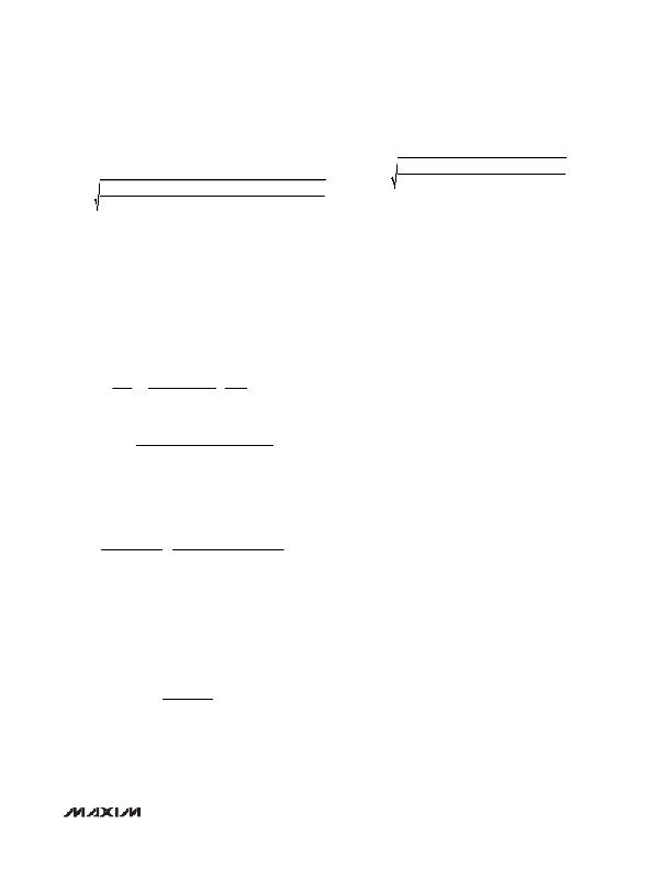
�I� PEAK� =�
�120mA� O� 2� O� 32V� O� (� 32V� +� 0.4V� -� 7V� )�
�3.3μH� O� 1.1MHz� O� 0.85� O� (� 32V� +� 0.4V� )�
�The peak inductor current in DCM is calculated with the�
�following� equation:�
�L� O� f� SW(MIN)� O� EO� V� OUT(MAX)� +� V� DIODE�
�The� inductor’s� saturation� current� rating� should� exceed�
�I� PEAK� ,� and� the� inductor’s� DC� current� rating� should�
�exceed� I� IN(DC,MAX)� .� For� good� efficiency,� choose� an�
�inductor� with� less� than� 0.1� I� series� resistance.�
�Considering� the� circuit� with� eight� 10-LED� strings� and�
�I� PEAK� =� =� 1.40A�
�Output� Capacitor� Selection�
�The� total� output� voltage� ripple� has� two� components:� the�
�capacitive� ripple� caused� by� the� charging� and� discharg-�
�ing� on� the� output� capacitor,� and� the� ohmic� ripple� due� to�
�the� capacitor’s� equivalent� series� resistance� (ESR):�
�V� RIPPLE� =� V� RIPPLE(C)� +� V� RIPPLE(ESR)�
�I� OUT(MAX)� ?� V� OUT(MAX)� -� V� S(MIN)� ?�
�?� V� OUT(MAX)� SW� ?�
�20mA LED full-scale current, the maximum load current�
�(I� OUT(MAX)� )� is� 160mA� with� a� 32V� output� and� a� minimal�
�input� voltage� of� 7V.�
�Choosing� a� CCM� operating� mode� with� LIR� =� 0.7� at� 1MHz�
�and� an� estimating� efficiency� of� 85%� at� this� operating� point:�
�and:�
�V� RIPPLE(C)� ≈�
�C� OUT� ?� O� f� ?�
�?� ?�
�?� 7V� ?� ?�
�?� ?� 0.85� ?�
�32V� -� 7V�
�32V� ?� ?� 160mA� � 1MHz� ?� ?� ?� ?�
�L� =� ?� ?� ?� ?� ?� =� 9.08μH�
�2�
�?� 0.7�
�In� CCM,� the� inductor� has� to� be� higher� than� L� CCM(MIN)� :�
�L� CCM(MIN)� =� (� 32V� +� 0.4V - 2� O� 7V� )� O� 13.7m� I� =� 5.5μH�
�2� O� 25.5mV� O� 0.9MHz�
�10� F� H� inductor� is� chosen,� which� is� higher� the� minimum� L�
�that� guarantees� stability� in� CCM.�
�The� peak� inductor� current� at� minimum� input� voltage� is�
�calculated� as� follows:�
�V� RIPPLE(ESR)� ≈� I� PEAK� R� ESR(COUT)�
�where� I� PEAK� is� the� peak� inductor� current� (see� the�
�Inductor� Selection� section).�
�The� output� voltage� ripple� should� be� low� enough� for� the�
�FB_� current� source� regulation.� The� ripple� voltage� should�
�be� less� than� 200mV� P-P� .� For� ceramic� capacitors,� the� out-�
�put� voltage� ripple� is� typically� dominated� by� V� RIPPLE(C)� .�
�The� voltage� rating� and� temperature� characteristics� of� the�
�output� capacitor� must� also� be� considered.�
�Rectifier� Diode� Selection�
�The� MAX17105’s� high� switching� frequency� demands� a�
�160mA� O� 32V� 7V� O� (� 32V� -� 7V� )�
�I� PEAK� =�
�+�
�7V� O� 0.85� 2� O� 10μH� O� 32V� O� 0.9MHz�
�=� 1.16A�
�high-speed� rectifier.� Schottky� diodes� are� recommended�
�for� most� applications� because� of� their� fast� recovery� time�
�and� low� forward� voltage.� The� diode� should� be� rated� to�
�L� DCM(MAX)� =� ?� 1-�
�(7V)� 2� O� 0.85�
�Alternatively, choosing a DCM operating mode will�
�lower� inductance� and� estimate� efficiency� of� 85%� at�
�this� operating� point.� Since� DCM� will� have� higher� peak�
�inductor� current� at� lower� input,� it� will� cause� current� limit�
�when� the� parameters� are� not� chosen� properly.� Consider�
�the� case� with� six� 10-LED� strings� and� 20mA� LED� full-�
�scale� current� to� prevent� excessive� switch� current� from�
�causing� current� limit:�
�?� 7V� ?�
�?�
�?� 32V� +� 0.4V� ?�
�O� =� 3.9μH�
�2� O� 1.1MHz� O� 32V� O� 120mA�
�3.3� F� H� inductor� is� chosen.� The� peak� inductor� current� at�
�minimum� input� voltage� is� calculated� as� follows:�
�handle� the� output� voltage� and� the� peak� switch� current.�
�Make� sure� that� the� diode’s� peak� current� rating� is� at� least�
�I� PEAK� calculated� in� the� Inductor� Selection� section� and�
�that� its� breakdown� voltage� exceeds� the� output� voltage.�
�Overvoltage-Protection� Determination�
�The� overvoltage-protection� circuit� should� ensure� the�
�circuit� safe� operation;� therefore,� the� controller� should�
�limit� the� output� voltage� within� the� ratings� of� all� MOSFET,�
�diode,� and� output� capacitor� components,� while� provid-�
�ing� sufficient� output� voltage� for� LED� current� regulation.�
�The� OVP� pin� is� connected� to� the� center� tap� of� a� resistive�
�voltage-divider� (R1� and� R2� in� Figure� 1)� from� the� high-�
�voltage� output.� When� the� controller� detects� the� OVP� pin�
�voltage� reaching� the� threshold� V� OVP_TH� ,� typically� 1.25V,�
�overvoltage� protection� is� activated.� Hence,� the� step-up�
�converter� output� overvoltage� protection� point� is:�
�_______________________________________________________________________________________�
�23�
�发布紧急采购,3分钟左右您将得到回复。
相关PDF资料
MAX17127ETP+
IC WLED DVR SIX STRING 20TQFN
MAX17149ETE+
IC LED DRVR 6CH STEP UP 16QFNEP
MAX17410EVKIT+
KIT EVAL FOR MAX17410 CTLR
MAX17605AUA+
IC MOSFET DRVR 4A DUAL 8UMAX
MAX1848ETA+T
IC LED DRIVR WHITE BCKLGT 8-TDFN
MAX1912EUB+
IC LED DRVR WHITE BCKLGT 10-MSOP
MAX1916EZT+T
IC LED DVR WHITE BCKLGT 6TSOT
MAX1986ETE+T
IC LED DRVR WHITE BCKLGT 16-TQFN
相关代理商/技术参数
MAX17105EVKIT+
功能描述:电源管理IC开发工具 MAX17105 Eval Kit RoHS:否 制造商:Maxim Integrated 产品:Evaluation Kits 类型:Battery Management 工具用于评估:MAX17710GB 输入电压: 输出电压:1.8 V
MAX17106ETN+
功能描述:PMIC 解决方案 PMIC for LCD RoHS:否 制造商:Texas Instruments 安装风格:SMD/SMT 封装 / 箱体:QFN-24 封装:Reel
MAX17106ETN+T
功能描述:其他电源管理 Integrated Circuits (ICs) Power Management - Specialized - IC REG STEP UP/HV STEPUP 56-TQFN RoHS:否 制造商:Texas Instruments 输出电压范围: 输出电流:4 mA 输入电压范围:3 V to 3.6 V 输入电流: 功率耗散: 工作温度范围:- 40 C to + 110 C 安装风格:SMD/SMT 封装 / 箱体:VQFN-48 封装:Reel
MAX17106EVKIT+
制造商:Maxim Integrated Products 功能描述:STEP-UP REGULATOR HIGH-VOLTAGE STEP-UP WITH TEMPERATURE COMP - Boxed Product (Development Kits)
MAX17107ETI+
制造商:Maxim Integrated Products 功能描述:- Rail/Tube
MAX17108ETI+
功能描述:LCD Gamma缓冲器 10Ch Scan Driver & VCOM Amp RoHS:否 制造商:Maxim Integrated 输入补偿电压: 转换速度: 电源电压-最大:20 V 电源电压-最小:9 V 电源电流: 最大功率耗散: 最大工作温度:+ 85 C 安装风格:SMD/SMT 封装 / 箱体:TQFN-38 封装:Tube
MAX17108ETI+T
功能描述:LCD 驱动器 10Ch High-Volt & VCOM Amp RoHS:否 制造商:Maxim Integrated 数位数量:4.5 片段数量:30 最大时钟频率:19 KHz 工作电源电压:3 V to 3.6 V 最大工作温度:+ 85 C 最小工作温度:- 20 C 封装 / 箱体:PDIP-40 封装:Tube
MAX17108EVKIT+
功能描述:电源管理IC开发工具 MAX17108 Eval Kit RoHS:否 制造商:Maxim Integrated 产品:Evaluation Kits 类型:Battery Management 工具用于评估:MAX17710GB 输入电压: 输出电压:1.8 V